Hacking the i3 battery modules connector – part 3
Test the wiring
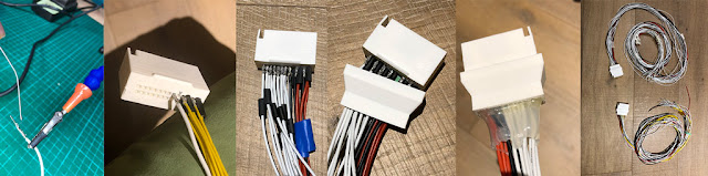
Now that I have all the connector wired up I need to make sure that every wires connects correctly to the battery.
I've used a basic digital tester to check the cables are connected and do make contact.
Be careful if you do that as these little wires are dangerous.
All was good a part a couple of labels for my sticky tabs that were swapped around for one of the two cables.
I'll be using the labels to connect to the BMS provided ribbon cables.
I hope that having now done these connectors work I'll have the flexibility to swap and reposition batteries as I like. I still have to see if to keep both batteries at the back or at the have one at the front. I'll let you know in future posts.
Having these connectors would also allow me to remove the electric kit and reinstall the original IC engine.
If you were to go through a similar process to mine, you'll find useful these tables in the picture that maps the relative voltage coming out from the wires and the a map of the cells and the colour of my cables*.
*note that your battery could use a different cable colouring and it could be configured in a different series that the batteries I've got.


Final touch
Connecting to the BMS ribbon cable balance wires

Next step


Comments
Post a Comment